All about BMW: BMW DIY, BMW series, BMW photos, BMW reviews...

E30 Lighted Rearview Mirror Retro-Fit

NOTE: Perform these steps at your own risk. All P/N's listed are a "best guess", so please double-check with your local dealer. These mods and repairs were performed on my US-Spec 1989 325i (12/88 prod date, M20/B25 engine) but there is no guarantee they will work on other E30's. These instructions are provided for entertainment purposes only!


BACKGROUND: It can be fairly frustrating when the only interior lighting is the two side headliner lightpods. In response, I found a used lighted mirror and proceeded to install and wire it up. If
Required Parts:
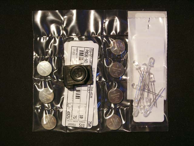
  • P/N 51 16 1 906 525 Interior rearview mirror with maplights (~$80 used or ~$150 new)
  • Short length of ~18AWG wire (speaker wire works)
  • Female connector plug and pins to match the attached harness. If you can't a prefect match, a 2-pin Molex #WMLX-101 connector works.
  • (2) Wire taps
  • Electrical tape

Required Tools:

  • Multi-meter
  • Wire cutter
  • Wire stripper
  • Soldering equipment
  • Precision screwdrivers
  • Crimping pliers

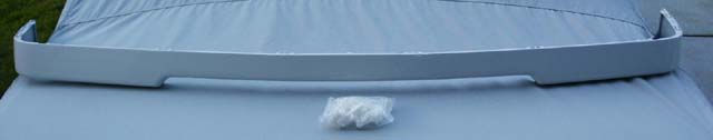
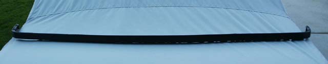
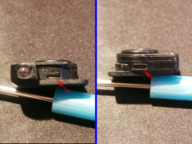
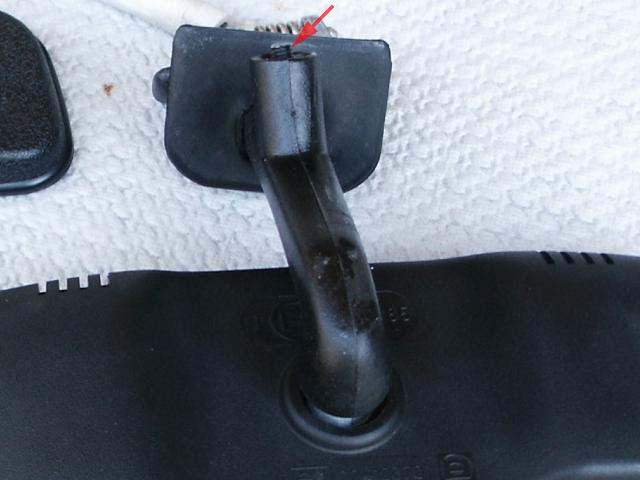
1. Before purchasing a used mirror, be sure it includes the thumbscrew that pushes against the windshield to prevent vibration. Because the mirror is heavier, vibration is a serious issue without this piece. The pic below shows a mirror with missing thumbscrew.

Please Note: Cabriolet owners will notice this mounting arm won't work on their cars. You will need to use the cabriolet arm instead which is beefier and can dampen the vibration without resorting to the thumbscrew. Click here for an excellent cabriolet install and wiring write-up by TNTS325ic.


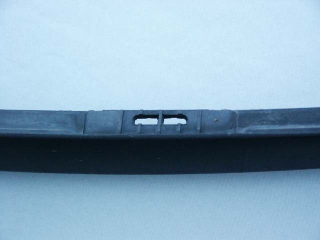
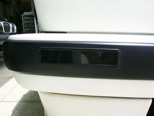
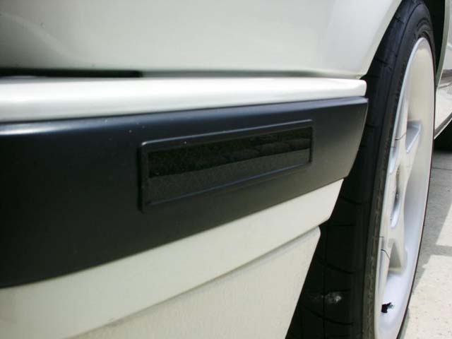
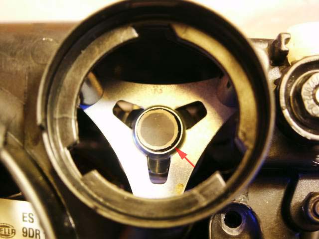
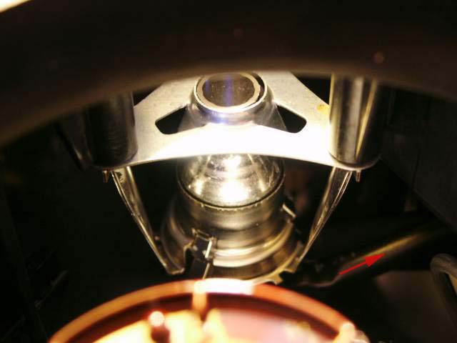
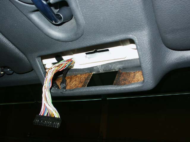
2. Remove the Active Check Control panel by slowly prying out the bottom flange till it releases. Unplug the wiring harness and completely remove the panel. Loosen the rubber grommet that hides the mirror stalk as it heads into the front headliner. The mirror removes by simply yanking it with some force till one of two spring-loaded pins retracts and the mirror pops off. Pulling it to one side or the other usually works for me.

Use a precision Philips-head screwdriver to remove the right-angle wiring cover over the harness to expose the plug.


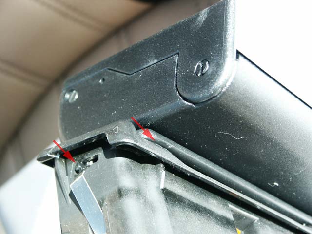
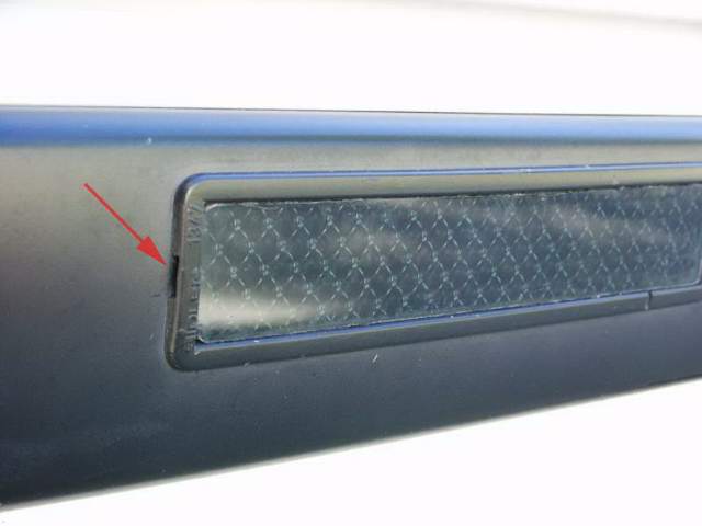
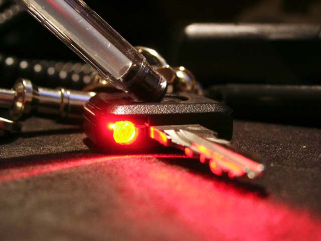
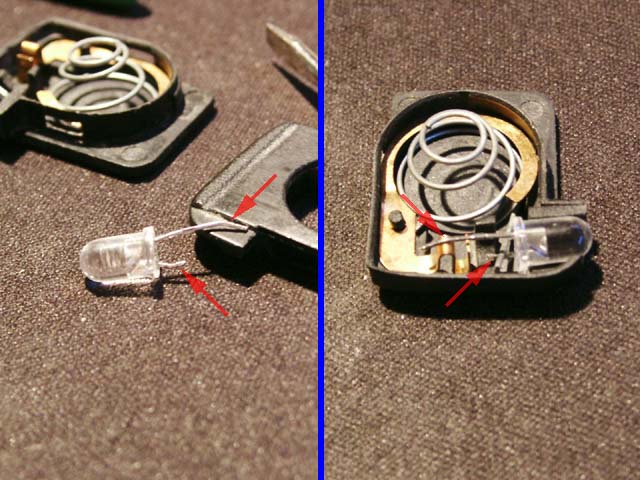
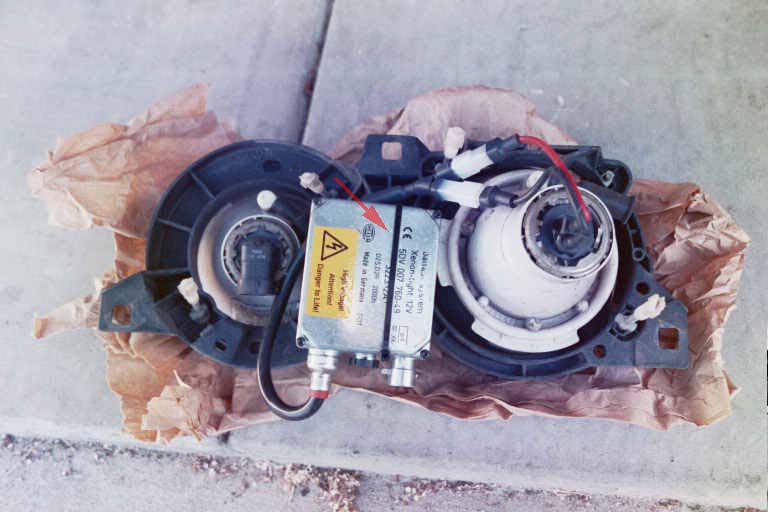
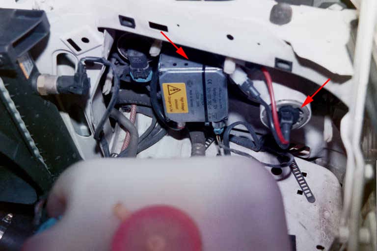
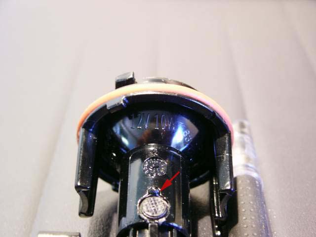
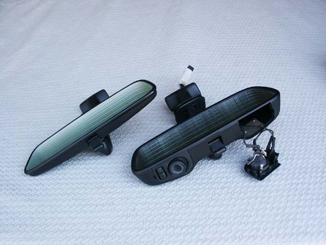
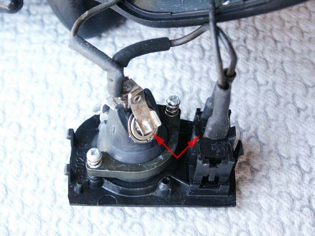
3. The lighted mirror has a short attached wiring harness for power. I pried out one of the light modules and used the multi-meter to determine which lead from the harness corresponded to the positive leads (see red arrows).


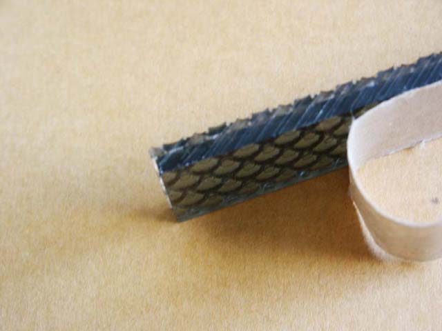
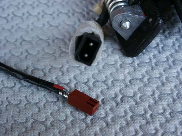
4. Using that information, I wired the 2-pin Molex connector which mates with the attached wiring harness (pictured). It's not a perfect fit between the two plugs, but they will lock in just fine. Another option would be to cut or splice into the mirror wiring, but I chose to keep it semi-stock. Use the ~18AWG wire to build the Molex adapter and leave the length long enough to splice into the Active Check Control wire harness as outlined below. Wrap the first 3-4" of wire with electrical tape for protection when routing.


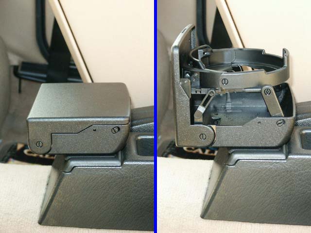
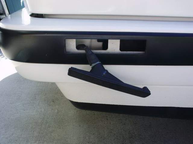
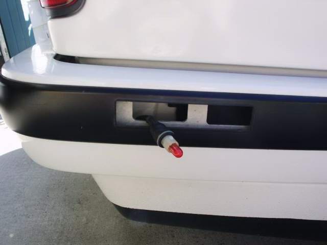
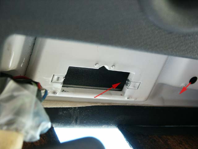
5. Route the cut ends of the new harness into the rectangular opening and back out thru the hole as pictured below. I might have used a zip tie as fish tape or possibly back-fed the wires before inserting them into the Molex plug. Leave a bit of slack in the wiring as shown in the 2nd pic below.


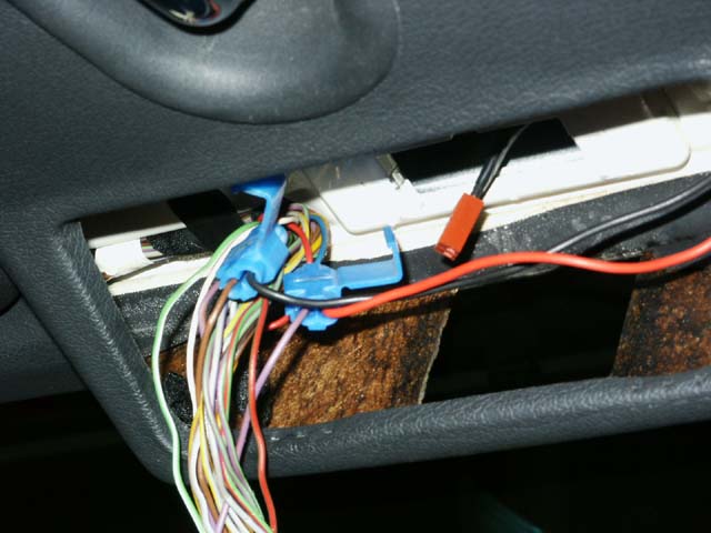
6. Use wire taps to connect the cut ends of the new harness to the Active Check Control wiring. Tap the negative lead into the brown ground wire coming off pin 9 in the harness.


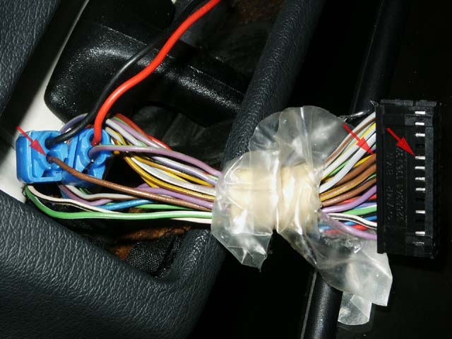
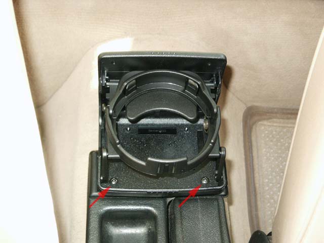
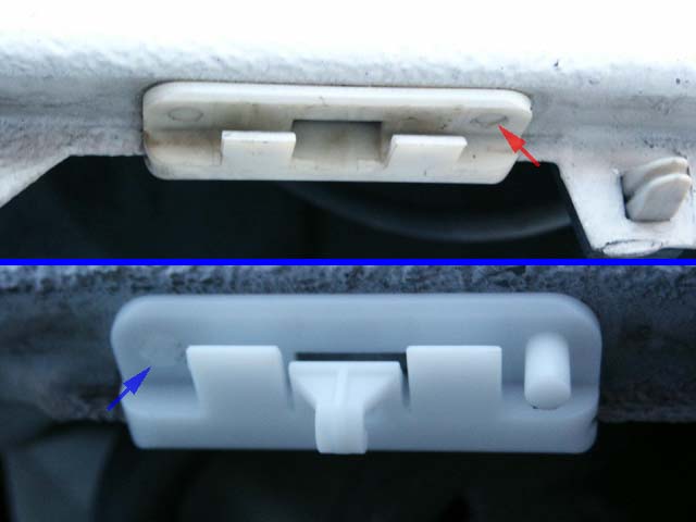
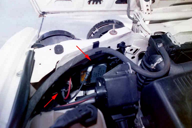
7. If you'd like the lights to be functional only when the key is turned, tie the positive lead into the violet/green-striped wire coming off pin 23 in the harness (see red arrows). If you'd like the lights to be available at all times, tie instead into the red/green-striped (pre-1987 models) or red (1987+ models) wire coming off pin 15 in the harness (see blue arrows).


8. Plug the Molex connector into the short mirror harness and push up on the mirror till it snaps into place. Getting the mirror snapped back into place might prove to be difficult. My advice is to wedge one side in first, then force the other spring-loaded side in. Take your time and use good judgement. Carefully reinstall the right-angle wiring cover over the plug and reconnect the Active Check Control panel to check for functionality of the panel and map lights in the mirror.


9. Remember to install the Active Check Control panel by fitting the top section first, then pressing the bottom flange in.

E30 Cup Holder


NOTE: Perform these steps at your own risk. All P/N's listed are a "best guess", so please double-check with your local dealer. These mods and repairs were performed on my US-Spec 1989 325i (12/88 prod date, M20/B25 engine) but there is no guarantee they will work on other E30's. These instructions are provided for entertainment purposes only!


BACKGROUND: It seems that just about every car has a cup holder nowadays. Some good, some crappy (can you say E39...), but at least they have something! I reviewed just about every E30 option, but couldn't find anything I thought would serve the following purposes: hold a variety of cups/bottles, unobtrusive when shifting (just say "no" to TracTop®), doesn't block seat movement, and integrates into the spartan E30 interior. My compromise was the Fischer C-Box universal cup holder which was available at Ultimate Cupholders for the best price (originally saw it in Griots Garage catalog for $17).

Since my rear ashtray was slightly cracked and there's no smoking in my car, I decided to mount the cup holder there as a test. So far, so good.


Required Parts:

Required Tools:

  • Drill and bits
  • Phillips-head screwdriver

1. For stability, I super glued the ashtray lid shut in four places total (see arrows).


2. Use a drill bit smaller than the supplied screws to drill out the two front pre-tapped holes in the cup holder after temporarily disconnecting the assembly. Properly position the cup holder and drill thru the ashtray lid. Use two of the supplied screws to attach them together fairly tightly.


3. Enjoy the results.


Warning/drawbacks:

  • Lost usage of the rear ashtray (obviously).
  • If you have rear passengers, you might want to remove the cup holder/ashtray assembly so they don't accidentally kick it if sliding across the seats.
  • When opening the cup holder, the ash tray will tilt back a tiny bit. As long as the cup holder isn't supporting a heavy container, I don't believe this will be an issue while in motion, but test it just to be sure.
If I decide it doesn't look good or work well, I simply have to buy a replacement for my previously-broken rear ashtray.

E30 "is" Lip Spoiler

NOTE: Perform these steps at your own risk. All P/N's listed are a "best guess", so please double-check with your local dealer. These mods and repairs were performed on my US-Spec 1989 325i (12/88 prod date, M20/B25 engine) but there is no guarantee they will work on other E30's. These instructions are provided for entertainment purposes only!


BACKGROUND: This is the OEM BMW spoiler on the 318is and 325is that can be easily fitted onto any late-model E30 that has the newer plastic bumpers and lower spoiler as shown in the pictures below. It replaces the black strip that normally comes on the 318i and 325i.
Required Parts:
  • P/N 51 71 1 968 488 - Lip spoiler [09/87+] (~$145 inc S&H from Maximillian Importing Co)
  • (Qty 10) P/N 51 71 1 979 334 - White spoiler clamps for light-colored cars [09/87+] (included by Maximillian)
    -OR-
  • (Qty 10) P/N 51 71 1 945 568 - Black spoiler clamps for dark-colored cars [09/87+] (included by Maximillian)

Required Tools:

  • Small flat-head screwdriver
  • Hammer

1. Remove the current black plastic lip (if it's still there - LOL) by pulling it straight away from the metal spoiler, starting at the sides first.


2. Remove/replace the current set of clamps by pushing the (2) expanding rivet pins (see red arrow) up and out of the old clamps using the screwdriver. The clamps should now pry out easily. Insert the new clamp and use the screwdriver and hammer (if necessary) to push the new pins up until they are flush with the clamp (see blue arrow).

Please note that if you've experienced any spoiler damage as I have, you'll probably notice broken or missing clamps as you can see in my comparison pic below. All my clamps had issues, so I installed new ones all around.


3. Snap the new spoiler onto the clamps and you are all done! Here's a pic of the connection points on the spoilers.


Before:

After:

You'll notice a very slight gap between the metal spoiler and new lip. It looks fine in person, but emphasizes the need to get either white or black clamps to match your car.

One word of warning on this mod: It'll make you want to paint the bottom black trim around the rest of the vehicle so everything matches... More bodykit pieces are also an option. :)

E30 1988-1991 E30 Smoked Sidemarkers

NOTE: Perform these steps at your own risk. All P/N's listed are a "best guess", so please double-check with your local dealer. These mods and repairs were performed on my US-Spec 1989 325i (12/88 prod date, M20/B25 engine) but there is no guarantee they will work on other E30's. These instructions are provided for entertainment purposes only!


BACKGROUND: It's possible to buy smoked front parking/turn signal lens covers (which I will be doing) and smoked rear tail lights, but what about smoked sidemarkers? I first bought some homemade clear lens replacements which were flimsy and poorly cut, so they had to go even before being installed. Here's my attempt at semi-homemade smoked lenses.
Required Parts:
  • Smoked plexiglass - 1/8" thick
  • K12 Clear prismatic plexiglass - 1/8" thick
  • Acrylic glue for bonding the plexiglass (check application with plastic shop)
  • Adhesive glue
  • (Pair) GE 194NA Amber sidemarker bulbs (found at Wal-Mart)
  • (Pair) GE 194R Red sidemarker bulbs (found at Wal-Mart)
Required Tools:
  • Precision plexiglass cutting machine or tool
  • Flat-head screwdriver
  • X-ACTO knife
  • Dremel or similar grinding tool
  • Hot glue gun

1. Visit your local plastic shop to either 1) Buy the first three parts listed for a completely DIY project OR 2) Be lazy like me and have them do everything but the lens installation.

I chose option 2 for obvious reasons. It's much more expensive to have them make it, BUT my lack of experience with plastics, plus having them precision cut the panels for me meant a near-flawless look and install. Also, bonding the two pieces correctly is important to avoid glue bubbles in the plexiglass sandwich.


2. Choose the color of the smoked plexiglass carefully. They had a few options, so I mulled over the idea of a completely blacked-out look and insufficient sidemarker light output. I ended-up with something in the middle. I had the plastic shop perform the process of glueing/bonding the two pieces of plexiglass and then had them precision cut into (4) 15/16" x 5-5/8" rectangles. I highly recommend you measure your own sidemarkers to double-check the sizing. Regardless, you'll need to grind a bit away, so be sure you err on the side of larger. If you decide to do this yourself, be sure you know what's involved in bonding and cutting plexiglass properly. Here's the net result.


3. Use the flathead screwdriver to carefully pry out the notched end of the sidemarker housings (see red arrow). Once it is popped out a bit, slightly pull the sidemarker towards that side to free the clip on the other end. Please note this pic was taken when I tried a clear laminate to protect the surface of the plexiglass from scratches. I didn't work out well and I removed the laminate and the markers have held up just fine without it.


4. Rotate the wiring plug counter-clockwise to remove the housing.


5. Don't let the wiring fall back into the bumper. Notice the red bulb here. To maintain the US DOT-approved look, you must install red bulbs in the rear and amber bulbs in the front. The aftermarket lenses aren't necessarily DOT-approved, but by maintaining the stock lighting coloring, you are at least "trying".


6. Somehow, knock or cut out the existing colored lenses and clean up the residue with the X-ACTO knife. This step was done for me by someone else, so I don't know the exact steps.
7. Carefully grind the edges of the new smoked lens to fit into the vacant sidemarker housing. Some or all of the edges will need tapering for a snug fit.
8. Use the adhesive glue to affix the smoked lenses into the housings. Use a glue that won't react with the plastics and turn them white-ish. Your plastic shop should be able to recommend something. I believe I used some type of strong rubber-cement in just the corners and the rest pressure-fit just fine.
9. Before reinstalling the housings, check for cracks due to heat above the bulb. I used the hot glue gun to patch it as you can barely see in the Step 4 pic.
10. Reinstall the sidemarkers with colored bulbs and enjoy the look.

At night, they are somewhat dimmer and possibly not DOT-legal, but they are definitely still visible as amber in front and red in back.

E30 LED Key Conversion

NOTE: Perform these steps at your own risk. All P/N's listed are a "best guess", so please double-check with your local dealer. These mods and repairs were performed on my US-Spec 1989 325i (12/88 prod date, M20/B25 engine) but there is no guarantee they will work on other E30's. These instructions are provided for entertainment purposes only!


THE GOAL: Chances are the little incandescent bulb in your original BMW key burned out years ago and finding a suitable replacement bulb at your local Radio Shack hasn't turned-up any good leads. I'm sure a trip to the dealer will produce a replacement bulb or key light assembly...but at a cost. Here's how to replace the bulb with a Light Emitting Diode (LED) that will last for years or decades. Here's one of the links to the original post.


Required Parts:
  • 5mm (T1-3/4) bright (high MCD) LED rated for 1.7V-3.7V ~20mA.
    • High-output Digi-Key 67-1612-NDM 2800MCD 30mA 1.7V 30° Viewing Angle red LED (Works great for me, but had to buy in bulk to be cost-effective.)
    • Medium-output Radio Shack 276-316 2600MCD 20mA 3.7V 30° Viewing Angle blue LED (Looks cool, but it's not quite bright enough - see pic below.)
    • High-output(?) Radio Shack 276-307 3000MCD 20mA 1.7V 12° Viewing Angle red LED (Untested, but very narrow viewing angle.)
  • A 16mm 3V coin-size lithium battery
    • Easy to find 55mHa CR1616 battery
    • Harder to find 125mHa CR1632 battery (Again, had to buy in bulk to be cost-effective.)

Required Tools:

  • X-Acto® knife
  • Small standard screwdriver
  • Wire cutters
  • Soldering equipment (optional)
I ordered 10 sets of the CR1632 batteries and 2800MCD red LEDs from Digi-Key. I changed LED colors because the output of my original blue LED was just "okay" and the Digi-Key tech verified that blue and white LEDs normally require the higher ~3.7V voltages. Since I can't find a 6V lithium battery (it seems to be okay to overdrive them) that will fit and I can't stack (2) 3V batteries, I switched to a lower-power, higher-output red LED.

The top picture shows the size difference between a new and original lithium battery. Bottom pic shows a relative light output difference between the blue and red LEDs I've tried.


1. Depress the BMW roundel and slide the light mechanism sideways to remove it from the key. Carefully use the screwdriver to depress the two mounting tabs on either side while applying slight force to separate the two halves. If the pieces don't fly apart, inside you'll find a small incandescent bulb, thick lithium battery, copper metal contact piece, and silver spring. Discard the bulb, recycle the battery, and remove the copper and silver spring pieces.


2. Use the X-Acto® knife to enlarge the bulb opening in the upper and lower plastic pieces. Take your time and test-fit regularly with the LED to get a perfect fit. The LED flange should be positioned just inside the housing lip.


3. The LED generally has an anode (longer) and cathode (shorter) leg which indicates polarity. Using the lithium battery, contact the anode to the (+) side and cathode to the (-) side to check the polarity and component functions.
4. Using the pic below as a reference, cut the shorter cathode leg (left lower arrow) so it cannot come in contact with the copper piece. Place the LED into the housing and reinstall the silver spring so the bent arm of the spring sits on top of the cathode (right lower arrow). If necessary, slightly bend the cathode upwards to ensure proper contact. Do not over-bend the leg as this might cause misalignment of the components.

Reinstall the copper piece so the anode leg rests on top of it (right upper arrow). Again, slight bending might be necessary to ensure proper contact. Trim off any excess anode leg. Check to be sure the cathode is still touching the silver spring and there is no contact between the spring and copper piece. The copper piece should barely hover above the spring thru its entire circumference.


5. Place the new lithium battery (+) side up onto the spring and center it with the roundel from the upper plastic piece. The roundel should have a keyed tab to help you figure out how it inserts into the upper plastic piece. Carefully squeeze the two plastic pieces together , while maintaining battery and component alignment. Proper placement of all components is crucial or you'll find that pressing the roundel doesn't always activate the LED correctly.


6. (Optional) Re-open the plastic housing and carefully solder the LED leg contact points to the respective spring and copper components. I didn't do so since the anode and cathode contact pressure seemed sufficient.
7. While depressing the roundel, slide the light assembly back into the key housing until it clicks into place.
RESULTS
Looks good to me!

E30 Independent Fog Lights

NOTE: Perform these steps at your own risk. All P/N's listed are a "best guess", so please double-check with your local dealer. These mods and repairs were performed on my US-Spec 1989 325i (12/88 prod date, M20/B25 engine) but there is no guarantee they will work on other E30's. These instructions are provided for entertainment purposes only!


BACKGROUND: Due to model year wiring differences, I found previous articles describing how to hotwire the fusebox for "fog lights without headlights on" probably wouldn't work on my '89 325i with ellipsoids. After digging thru schematics and probing with a multi-meter, I found a workable solution.

This mod will not work on many E30's, so proceed only if you have sufficient car electronics experience to determine if this is viable on your particular vehicle.

Final warning is this mod will allow the fogs to be left on with the parking lights on and no keys in the ignition. Due to the potential for unintentional battery drain, only proceed if you want the convenience of front lighting with no keys. Do not perform this mod if you might leave the parking lights on without noticing the green fog light indicator and entire dashboard lit up. At the bottom I discuss a second, untested method to have independent fogs with parking lights on and the key in the ignition.

Previous procedures I've read about leave the fogs on even when the high beams are activated. I prefer to follow the BMW design principle of unloading unnecessary power when the high beams are needed, so this mod will disable the fogs when the highs are on.


Required Parts:
  • Small length of 16AWG wire

Required Tools:

  • Multi-meter
  • Wire cutter
  • Wire stripper
  • Soldering equipment
  • Flat-head screwdriver

1. Verify your fusebox has the exact same K3, K4, and K8 relays. This would be the first indication if this method is even feasible on your vehicle. If you have the same colored relays with the same schematics molded on the relay covers, it's a bit safer to proceed.

Use the screwdriver to carefully pry out the K4 low beam and K8 fog light relays. Disconnect your battery prior to doing so if you want to be safe. Reconnect the battery before the next step.


REMINDER: The steps below are crucial to determining if your car's circuitry is similar to the car described here. If anything including relay appearance or circuit test results does not match 100%, do not continue unless armed with detailed schematics of your car's wiring diagram and enough knowledge of car electronics to avoid damage to the circuitry. Severe damage to your vehicle and persons performing the work can result.

2. Use a multi-meter tool to confirm fusebox K4 terminal 87 connects to K8 terminal 30. The terminal numbers are stamped on the bottom of the relays for reference. Probe for 12V hot at all times on K4 terminal 30. To pre-test this mod and only after all the above check out as correct, use a length of wire to bridge terminals 87 and 30 of fusebox position K4. Relay K4 should be removed and relay K8 installed during this test. The fog switch should work when the parking lights are on.


3. Solder a short length of wire between K4 terminals 87 and 30 close to the body of the relay as shown below.


4. Reinstall the relays, with K4 not seating completely due to the soldered wire. Use care when installing K4 because I ran into a issue by pushing forcefully down on the relay, where the low beams came on and stayed on even w/ the keys removed from the ignition. I'm guessing the extra wiring I soldered was pushing up on the base of the relay, causing the internal contacts to touch and engage the low beams. I simply backed off on the install pressure and everything has been fine. Turn on the parking lights + fog switch and enjoy the results.


Alternate Method:
If you wish to modify the procedure to only allow independent fogs when the ignition is on (for safety reasons), find a sufficient gauge+fused switched 12V line and attach it to K8 terminal 30 and do not modify K4 at all. I have not tested this and warn of easily bridging switched power from K8 terminal 86 without researching the gauge and fuse rating that connection uses. E-mail me if you are going to attempt this and possibly I can assist.

E30 Xenon Bulb & Ballast Installation

NOTE: Perform these steps at your own risk. All P/N's listed are a "best guess", so please double-check with your local dealer. These mods and repairs were performed on my US-Spec 1989 325i (12/88 prod date, M20/B25 engine) but there is no guarantee they will work on other E30's. These instructions are provided for entertainment purposes only!


THE GOAL: To cleanly install Xenon ballasts and 9006 bulbs. (Update 07.05.02) I've determined that I need to move my bulbs back a few millimeters to achieve the best light output. I'll be working on a solution over the next few weeks.


1. In the engine compartment, remove the (2) body fasteners that hold the rear black plastic light cover in place. Unplug the high and low beam electrical connectors from the back of both bulbs.
2. Unfasten (3) clips and (2) screws to remove the black grill surround. Remove the (3) large phillips-head screws that hold the headlight housing to the body and remove the ellipsoid low beam and high beam assembly. The mounting flanges are normally made of plastic and should have indents from the mounting screw and washer, which will aid in semi-proper alignment following reassembly.


3. I used a long zip tie to secure the ballast to a semi-flat portion of the headlight assembly between the two housings. The ballast wire was then routed to the Xenon bulb which fits perfectly in the ellipsoid 9006 socket.


4. Screw the headlight assembly back onto the car. Be sure to realign the three mount points as closely to original as possible.


5. Repeat the steps for the passenger side.


6. Plug the low beam electrical connector into the ballast, and the high beam connecter back into the high beam bulb.
7. I had to upgrade my fuse #13 and #14 from 7.5amp to 10amp to handle the extra draw from the ballast when igniting the arc. After the lamp is lit, it actually draws less current than stock halogen bulbs.

8. After testing and the "wow" factor is over, reinstall the rear light covers. The driver-side cover should fit perfectly, but I had to modify the passenger-side cover a bit to clear the ballast. I carefully heated the black plastic with a heat gun and bent it where necessary for clearance.
9. Proper beam alignment is crucial to reduce the chances of blinding oncoming traffic. Check on the web for specific instructions on aiming Xenon lights for 4-beam cars. An example can be found here.

RESULTS
I was pleased with the dramatic increase in light output and the new, "cool" white beam look. The light emitted isn't as bright as most high-end OEM Xenon systems on today's passenger cars, and I believe some of it has to do with the fact that my 1989 ellipsoid lenses aren't beam pattern matched for Xenon bulbs. So I don't get all the benefits of high intensity discharge lighting, but it's still a noticeable improvement. Other benefits are a wider beam pattern and street signs tend to reflect better off of Xenon light versus halogen light.

Is this upgrade for everyone? No.
Some might find the cost prohibitive and generally not worth the trouble. There are a number of "pure white" halogen bulbs on the market which mimic the white color and also produce a decent amount of light. I just figured that I'm getting old and my eyes are getting worse, hence the need for maximum lighting! ;-) I picked up the set for $450 which is moderately cheap for Xenon lighting kits.

| Value for the money: 6 | Added safety benefit: 8 | Cool factor : 9 |

Here's some pictures so you can decide for yourself. Can you guess which side has the Xenon lighting?


Fully locked and loaded.


E39 CELIS Light Source

NOTE: Perform these steps at your own risk. All P/N's listed are a "best guess", so please double-check with your local dealer. These mods and repairs were performed on my US-Spec 1989 325i (12/88 prod date, M20/B25 engine) but there is no guarantee they will work on other E30's. These instructions are provided for entertainment purposes only!


The OEM Hella CELIS (aka Angel Eye) light source is a 12V 10W halogen lamp in a reflector housing which shines into a collector lens leading to the fiber-optic lines.


The bulb is holder is plastic-welded together, so replacing the bulb would require breaking the weld.


The halogen lamp gets focused onto this concentrator lens (see red arrow). The concentrator lens is spaced from the halogen reflector assembly by approximately 1".


Here's the concentrator unit. The black tubing heading off to the right leads to the four fiber-optic leads in the two CELIS rings.